
Making a Battery Interrupters With 2 Separate Wires

Below I have explained how to make a battery interrupter with 2 separate wires.
What You Need:
3.5 mm Female Jack
22-24 gauge speaker wire
Circuit board - I have found that the circuit board on amazon that is 1.5 mm thick is a little too thick. I am currently looking for thinner double sided copper sheets that are insulated. I have found these two: (1) Tinkersphere (2) Digi-Key Electronics but I have never used either, so I am not sure if it works.
You can also use two sheets of copper foil and a thin piece of cardboard or chipboard.
Battery operated toy
Switch (for testing & using the toy after adapting it)
Tools
Utility knife
Soldering iron
Solder
Wire strippers
Tin shears
Metal file (optional)
Note: The images on this page are from different videos and the the colors of the wires will change. I used these images because I wanted to give you the clearest pictures.
Cut 2 Wires to Size
Use 22 to 24 Gage stranded wire and cut between 6-8 inches depending on the project
For some projects you can use solid wire. I use this for circuit soldering onto a circuit board, or for battery interrupters that will permanently live in a toy that has hard plastic, such as the bubble machine and the art spinner, because for these projects there is a lot less movement then in a plush toy.
Important: I tend to cut it a little longer than I need it to be and then I will cut down the other side when attaching it to the copper plate. This was extremely useful when I was new to soldering. This allowed me to make mistakes and instead of tossing the entire piece I could just cut it down and redo it.


Image from a different battery interrupt

Image from a different battery interrupt
Strip The One End of Each Wire.
Find the number gauge wire you are using on you wire strippers. Then place the wire in that groove of the wire stripper, so that there is about 1/4 inch on one side. That will be the side you are going to strip or remove the protective plastic insulator from, revealing the metal wire.
Important: Be careful not to cut any of the wires in the process. I have definitely done this many times! If this happens, you can cut this part off and try stripping it again. That’s why I cut the wires longer than needed.
Connect The First Wire to The Jack
If you are using a stranded wire, you are going to want to twist the wires together.
Feed one of your wires through the tall pin, leaving some of the exposed wire visible on the other side. Then bend it backwards so it becomes parallel with the yellow wire. You will then pinch the exposed metal on both sides of the tall pin and twist the metal strands together.


Solder The Wire On to The Jack

Now place the jack into one of the alligator clips on you helping hands. Then, take the soldering iron into your dominant hand and the solder into the other and hold the solder and the iron to the wire for several seconds. I start with my soldering iron on medium but you may need to adjust it as you go. Once some of the solder melts onto the wire, pull back the solder but leave the iron there for an additional few seconds.
IMPORTANT NOTES:
You should notice the solder on the jack becomes shiny, this means it is heated up enough.
You really don’t need a lot of solder, I am definitely guilty of this.
Add Heat Shrink Tube


Cut the heat shrink tube to the desired size. Then put it on the wire and pull the heat shrink tube down so it covers all the exposed metal wires.
Next, use a fire source to shrink the tube.
For each individual wire, you can use a relatively small heat shrink tube. I used the 3 or 4 smallest sizes that came in kit of heat shrink tube I bought. I believe it was 1/24” (1mm), 1/16” (1.5mm) and 1/13” (2mm) tubes
Recommended Step: Folding Over the 2 Side Metal Pieces on The Tall Pin.
The reason this step is “recommended” and not an absolute necessity is because by doing this step, you are further reducing the likelihood of the wires accidentally touching which will complete the circuit. You have already added heat shrink tube which does the same thing so this is not totally necessary but highly recommended so things don’t turn on/off without switch activation.
This step can be a little difficult. I use the tip of my wire strippers that looks sort of like pliers to fold over the side metal pieces on the tall pin. I recommend doing it one piece at a time, and do it little by little and repositioning the wire strippers as you go. Then, do the same thing on the other piece.


Connect The Second Wire to The Jack
If you are using a stranded wire, you are going to want to twist the wires together.
Feed the second wire through one of the small pins, leaving some of the exposed wire visible on the other side. Then bend it backwards so it becomes parallel with the red wire.


Now pinch the exposed metal on both sides of the small pin and twist the metal strands together.

Fold The Wire Over And Twist


Solder The Wire On to The Jack

Now place the jack into one of the alligator clips on you helping hands. Touch the solder and the soldering iron to the wire on the jack. Once some of the solder melts onto the wire pull, back the solder but leave the iron there for an additional few seconds. Make sure the wire is straight, otherwise it will be hard to put the cover on.
IMPORTANT NOTES:
You should notice the solder on the jack becomes shiny, this means it heated up enough.
You really don’t need a lot of solder, I am definitely guilty of this.
Add Heat Shrink Tube
Pull the heat shrink tube down so it covers all the exposed metal wires.
Next, use a fire source to shrink the tube.
For each individual wire, you can use a relatively small heat shrink tube. I used the 3 or 4 smallest sizes that came in kit of heat shrink tube I bought. I believe it was 1/24” (1mm), 1/16” (1.5mm) and 1/13” (2mm) tubes


Now take a larger heat shrink tube to cover both of the wires close to the jack. This will make it more protected when you replace the jack’s cover. For this step, I used the larger tube that came with the jack I purchased, or can use one from the set. I’d say probably 9/64” (3.5mm) or 5/32” (4mm) but you can play around with your tubing sizes.
Add the Jack Cover
You feed the wires through the larger opening. It can be a little annoying to fit both of the wires in at the same time as they can get caught or stuck, so I recommend doing one wire at a time.


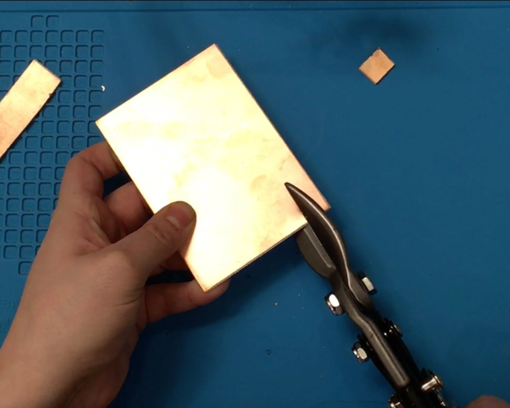
Cut The Circuit Board
Use Tin Snips to cut the circuit board. The size you should cut depends on the size of the battery you will be using it for. To figure out the exact size, I recommend cutting a few different sized pieces and seeing if it fits.
After making the batter interrupter, you may find that you will have to cut the circuit board down a little more.

I use a circuit board for my copper plates for in my battery interrupts. When I first started I bought circuit board I bought ones that were 1.5MM Thickness but these are kind of thick so I am currently trying to find a thinner option. I once received a very thin cooper plate from a former co-worker, who received it from a former coworker so where it originally came from was lost. I do hope to find it one day and am trying different options.
Additionally, there are other way to make the copper plate which I hope to discuss one day.
File Down Sharp Side and Round the Corners

After cutting the circuit board, you are going to want to file down the rough edges and corners on the piece of board you are going to be using for the copper plate of your battery interrupter.
Add a Drop of Solder to Each Side of The Circuit Board
Now you are going to want to add a drop of solder to each side of the circuit board.

You are going to want to place the solder dots high enough up so that they don’t interfere with the battery placement but low enough so that the solder does not accidentally drip on the edge or the other side of the circuit board.
Important Note: if solder drips from one side of the circuit board to the other, the battery interrupter will not work.
To help avoid this you can off set the dots of solder a few millimeters on each side of the circuit board. Don’t put the dots of solder directly in the center of the board! Rather, put one close to one side and the other close to the other side.

How to know if the solder is ready: you will know because the solder will get this shinny, metallic look to it.
Add Heat Shrink Tube to Each Wire
You are going to want to add a small piece of heat shrink tube to each of the wires.
Make sure that you move it down the wire past the exposed portion so that it does not accidentally shrink when soldering on the wire in the next step.

Attaching the Wires


When you attach the wire you might want to cut down some of the exposed wires if you find any.
When attaching the wires, I use the tweezers in order to bend the exposed wire so that it is not laying completely flat on the copper plate. This will leave a little space for the heat shrink tube, as explained in the following step.
Solder The Two Wires Onto The Copper Plate

Shrink The Heat Shrink Tube
Now you are going to have to unclamp the wire so that you can move the heat shrink tube up. Pull it up so that you can protect the exposed wires near the copper plate.
You are going to want to make sure that part of the heat shrink tube is placed on the copper plate. This will ensure that the exposed metal on each wire doesn’t touch. This step can be difficult. In order to do this, I make sure that the part of the wire I just soldered has a little space where there is no solder.
Then use heat to shrink the tube.

Repeat the Previous Two Steps With The Second Wire

Trim The Exposed Wire

Solder Into Place

Shrink the Heat Shrink Tube